3D Printed ski Jig

elm.

Active member
I recently made a 3D printed ski Jig for a pair of STH's. It worked ok, but could be improved. Advice is welcomed.

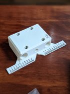
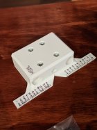
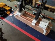
There are three 3D printed pieces. The heel piece jig, midsole finder, and toe piece jig. The prints took about 14hrs total and maybe 1.5 hours of design work. It works with a long threaded rod down the middle that moves the upper plate of the jig forwards and backwards. The copper rods hold the entire jig straight and allow the jig to move forwards and backwards. I used a 5/16's 3ft threaded rod, and two 2ft 1/4" copper tubing. Total cost was around $15.

980035.jpeg

The hole pattern was measured off of the STH's with a pair of calipers. In hindsight I should have photocopied the bottom of the binding to get more accurate measurements.

First, you mount the bindings on the jig using some nuts and bolts. Then you turn the threaded rod until you get the correct size for your boot and then click your boot in. Then you lock the toe piece from moving with a couple of nuts that are on the rod.

Then you slide the middle piece so that it is lined up with the midsole of your boot, then lock it in with a couple of nuts. This part is just done by eyeballing the mark on the piece with your boot.

980034.jpeg

After the length and midsole are locked in place, you take the boot out and put the jig over the top of the ski. Next draw a centerline down most of the ski length wise on some tape using a center finder. Line up the midsole piece with how far back you want to mount. Then line up the dashes on the ends of the jig with the centerline. Hold the jig down then drill/pencil in some marks.

980037.jpeg

Now the ski can be fully drilled and mounted.
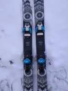
980038.jpeg

The mount turned out good except for the fact that one of the bindings has about a 0.5 degree angle to it. I haven't skied them yet, but I don't see this as being a huge issue.

Some improvements would be a better way to find the midsole of the boot and the center of the ski, and also a better way to clamp it down.
 
On the topic of hole location accuracy, I would recommend downloading a paper template and scaling it into your cad program rather than measuring from the bindings. Maintaining precision in mating 3d printed parts is difficult and I like your use of readily available and relatively precise components with the copper tubing. Playing with the orientation of the printed parts could help with accuracy as well.

Maybe rather than adjusting the midsole location with that center piece, you could have graduations on the toepeice and heelpeice that you align together, essentially just a 3d version of a paper template id that makes sense
 
14197341:No.Quarter said:
On the topic of hole location accuracy, I would recommend downloading a paper template and scaling it into your cad program rather than measuring from the bindings. Maintaining precision in mating 3d printed parts is difficult and I like your use of readily available and relatively precise components with the copper tubing. Playing with the orientation of the printed parts could help with accuracy as well.

Maybe rather than adjusting the midsole location with that center piece, you could have graduations on the toepeice and heelpeice that you align together, essentially just a 3d version of a paper template id that makes sense

Yeah I was planning on putting the pdf into cad for next time.

The graduations is an interesting idea for the midsole. I'm not sure if my printer is big enough for that, though.
 
I had something similar modeled up for the pivots but never got around to finishing it.

The sliding pieces in the middle were supposed to have the sole BSL on them and you would just slide the pieces to match up the length. I really just need a good self centering and clamping method to put on them and print them and print em out. I modeled mine off the binding freedom paper template, extruded up from that and went about the rest from there. Cool to see someone else had the same idea and went through with it though!

980072.jpeg
 
14197392:Corey_O132 said:
I had something similar modeled up for the pivots but never got around to finishing it.

The sliding pieces in the middle were supposed to have the sole BSL on them and you would just slide the pieces to match up the length. I really just need a good self centering and clamping method to put on them and print them and print em out. I modeled mine off the binding freedom paper template, extruded up from that and went about the rest from there. Cool to see someone else had the same idea and went through with it though!

View attachment 980072

Sweet idea for the bsl cause then the midsole is accounted for. Hardest part for me was getting the jig lined up straight on the ski.

I think if the jig could clamp onto the edges/sidewalls and self center then it would be awesome. Might be as simple as putting some bolts on the side with some plates and counting the rotations of bolts so they're even.
 
14197397:elm. said:
Sweet idea for the bsl cause then the midsole is accounted for. Hardest part for me was getting the jig lined up straight on the ski.

I think if the jig could clamp onto the edges/sidewalls and self center then it would be awesome. Might be as simple as putting some bolts on the side with some plates and counting the rotations of bolts so they're even.

I was thinking about using the concept below somehow with a thing in the middle that pivots to the size of the sidewalls

980076.jpeg
 
14197324:The.Fish said:
inb4 the tuning guys destroy this thread

actually im givin him props

a set of digital calipers

and one more measurement

before drilling and he woulda nailed it

with 10x steeze points vrs paper templates
 
Good on you dude the industry needs more R&D on DIY type shit. That left toe piece definitely does have an angle to it so if you can I’d test it out to make sure you can release safely but other than that I’m jealous that you’re handy enough to do something like that
 
This past week I 3d printed a pivot plates for my local shops jigarex because their normal jig cant mount 110+ underfoot skis, it worked but minor adjustments need to be made still.

I like your design though.
 
This is a great idea. Lots of libraries around the nation are starting to have 3d printers for use so this would be really feasible for most people
 
Not bad but sounds like you’re over thinking it plus I can tell your toe piece is off center. Buy a tech a case of beer and we’ll do it without it being that much of a headache.
 
14197951:EvanMeyer said:
Not bad but sounds like you’re over thinking it plus I can tell your toe piece is off center. Buy a tech a case of beer and we’ll do it without it being that much of a headache.

Thanks...dick
 
OCD kicking in, are thoose bindings really as crooked as pic suggested ? can we get a center image from top of each ski? not trying to be rude, just wondering of optical illusion or not.

as for 3d printing jig, I think it will be a thing for sure. What you could do to improve it, are metal inserts, like the ones jigarex has, so the drill and tap doesnt eat out the holes to quick.
 
Sometimes people want the headache. Don’t get me wrong I think techs have their place, and a lot of people benefit from them, but at the same time some people want to figure it all out for themselves, and make projects out of stuff like this. Not to mention some places it’s hard to find good techs. That was my case at least. Good luck finding someone good in VA, and if you do they’ll just try and talk you into mounting your skis to -6

14197951:EvanMeyer said:
Not bad but sounds like you’re over thinking it plus I can tell your toe piece is off center. Buy a tech a case of beer and we’ll do it without it being that much of a headache.
 
14197392:Corey_O132 said:
I had something similar modeled up for the pivots but never got around to finishing it.

The sliding pieces in the middle were supposed to have the sole BSL on them and you would just slide the pieces to match up the length. I really just need a good self centering and clamping method to put on them and print them and print em out. I modeled mine off the binding freedom paper template, extruded up from that and went about the rest from there. Cool to see someone else had the same idea and went through with it though!

View attachment 980072

I really like those midsole alignment features, but it seems they could be greatly simplified
 
14198229:anders_a said:
OCD kicking in, are thoose bindings really as crooked as pic suggested ? can we get a center image from top of each ski? not trying to be rude, just wondering of optical illusion or not.

as for 3d printing jig, I think it will be a thing for sure. What you could do to improve it, are metal inserts, like the ones jigarex has, so the drill and tap doesnt eat out the holes to quick.

The pic makes them look worse cause the left ski is tilted inwards. I've asked friends to take a look and they only notice when I mention it.
 
14198823:tristan0 said:
I will straight up buy give you my soul if you can print a Pivot Jig

I am going to make a pivot one probably within the next month and I'll post it here with the updates
 
I made a second version of these for a pair of pivots. Before you read on note that I did not actually end up using these to drill my skis, but instead used a paper jig.

I added a scale to the ends of the new jig, made the drill holes smaller for a pilot bit, put the nuts on the top (super glued in), and made the overall profile shorter and smaller.

985564.jpeg

985565.jpeg

It functioned the same way by putting the boot in and setting the forward pressure and placing the midsole in the right location. Then locking it in and taking the boot and binding off.

985566.jpeg

I drilled into a piece of 4x4 and I think the big problem was that the wood was just too soft. I didn't use a punch and the bit walked so the hole pattern was just slightly off. I mounted with binding freedom on this setup and learned that binding freedom or quiver killers add another level of accuracy to mounting skis.

985567.jpeg

After all this I just didn't feel confident enough in the jig. It was soooo close and I think I could've gone back and fixed a few things, but I was in a rush to get the skis mounted and used a paper jig. The binding freedom took me a long time to mount and it didn't help that the old holes on the ski made me have to mount at -3.5 on my opus's.

In the future, I think a couple pieces of T slotted extruded aluminum with some aluminum rectangles would be the best way to create a jig. A rip off of jigarex. I could hear the plastic cracking on my jig when I mounted the boot. It probably didn't help that my print settings were optimized for speed rather than accuracy and strength.
 
Back
Top