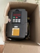
ATTENTION ELECTRICAL ENGINEERS

Thegenericskier

Active member
I am in dire need of help of my electrical system for my CNC router I have just fried everything on my wiring system that was working a week ago before it all got moved into an electrical box. Those who would like to help I am open to a video type call to walkthrough my wiring
 
14439612:freestyler540 said:
Without the plans, Im no use. Get me the diagrams and plans and maybe I could care.

This is the wiring diagram for the PSU and inverter. It was working last week before I disconnected everything and put it into an enclosure. All the wiring on the physical side is the same too

1043501.png
 
14439795:Thegenericskier said:
This is the wiring diagram for the PSU and inverter. It was working last week before I disconnected everything and put it into an enclosure. All the wiring on the physical side is the same too

View attachment 1043501

looks like those wires are all kinked up! try to get em a bit straighter see if the energy flows a little better after that
 
1043724.jpeg

R=L

T=N

UVW to spindle, if polarity is incorrect, just flip two of the phases.

ground to the screws mounting the vfd and the ground the panel/box.

do you need a separate 24v ps to power up the vfd? its good to get a safety relay that stays powered on after you hit the estop to let the vfd ramp down the spindle instead of free wheeling after power loss.

make sure your parameters are not crazy. use 3s for ramp up ramp down and that the frequency doesnt go past nominal rating of the motor. and maybe you can set the current limit on the vfd too. set that to nominal value of the motor.
 
14440522:ajbski said:
View attachment 1043724

R=L

T=N

UVW to spindle, if polarity is incorrect, just flip two of the phases.

ground to the screws mounting the vfd and the ground the panel/box.

do you need a separate 24v ps to power up the vfd? its good to get a safety relay that stays powered on after you hit the estop to let the vfd ramp down the spindle instead of free wheeling after power loss.

make sure your parameters are not crazy. use 3s for ramp up ramp down and that the frequency doesnt go past nominal rating of the motor. and maybe you can set the current limit on the vfd too. set that to nominal value of the motor.

Thank you! My VFD settings were pretty basic I was just following the manual.

1043725.jpeg

It might be hard to trace but my VFD and 24v PSU share the same live neutral and ground and I had it wired like your image shows. Not really sure as to why it blew up in the first place since it worked just fine the other week
 
14440523:Thegenericskier said:
Thank you! My VFD settings were pretty basic I was just following the manual.

View attachment 1043725

It might be hard to trace but my VFD and 24v PSU share the same live neutral and ground and I had it wired like your image shows. Not really sure as to why it blew up in the first place since it worked just fine the other week

get a multi meter and check the p.s is still giving 24v.

i would strongly suggest putting fuses (or circuit brakers more expensive) before all components while you are figuring out the wiring. it will save you money and time in the long run.

take a pic of the name plate on the motor... im confused why you are trying to run a three phase async. motor with a dc ps???

also those ps can only take so much current. if you are powering the steppers with that power supply, i wouldnt use it to power to spindle too.
 
14440532:ajbski said:
get a multi meter and check the p.s is still giving 24v.

i would strongly suggest putting fuses (or circuit brakers more expensive) before all components while you are figuring out the wiring. it will save you money and time in the long run.

take a pic of the name plate on the motor... im confused why you are trying to run a three phase async. motor with a dc ps???

also those ps can only take so much current. if you are powering the steppers with that power supply, i wouldnt use it to power to spindle too.

I have both the PSU and VFD running from the wires coming from the wall. If I go with a circuit breaker route what would the best types be?

1043735.jpeg
 
it looks like you have everything right. the only thing i dont get is where the ground terminal (yellow crimp right most side) is going.... i would use the red wire you have strapped to the enclosure. also the the ground from the motor cable should connect there too.
 
14440548:ajbski said:
it looks like you have everything right. the only thing i dont get is where the ground terminal (yellow crimp right most side) is going.... i would use the red wire you have strapped to the enclosure. also the the ground from the motor cable should connect there too.

That’s how I originally had it, that image was taken when I had everything wired up. Thanks for the help
 
14440550:Thegenericskier said:
That’s how I originally had it, that image was taken when I had everything wired up. Thanks for the help

yea no worries. youve come a long way since the original machine. good work.

on another note, i probably wouldnt try to run that motor at 400hz right off the bat. start with 200 and getting running with 200. it will have less torque, but if you are using a small bit, it wont really matter too much.

at my company we run bigger VFD than necessary too. if the motor is rated up to 3hp we go with a 5hp vfd... just to stay away from the current limit of the vfd. we have problems that the vfd is stalling when the motor is under load (on start up or while cutting)
 
14440555:ajbski said:
yea no worries. youve come a long way since the original machine. good work.

on another note, i probably wouldnt try to run that motor at 400hz right off the bat. start with 200 and getting running with 200. it will have less torque, but if you are using a small bit, it wont really matter too much.

at my company we run bigger VFD than necessary too. if the motor is rated up to 3hp we go with a 5hp vfd... just to stay away from the current limit of the vfd. we have problems that the vfd is stalling when the motor is under load (on start up or while cutting)

Sweet, biggest sized bits I plan on running are 1/4 inch. Got about 20 days to get everything running again before my national competition
 
14440536:ajbski said:
https://www.se.com/ca/en/product/M9P22606/multi-9-n40n-mcb-1p-+-n-6-a-c-curve-240-v-10-ka/?parent-subcategory-id=86933&range=1104-multi-9&selected-node-id=12367768059

something like that... this one is for single phase AC and trips @ 6 amps.

I was reading through the VFD manual and it was saying some of wiring an electromagnetic contractor before power reaches the VFD. Is this something you would reccomend? If so do I wire that with a circuit breaker?
 
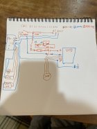
Sorry for the poor handwriting but this is my new wiring diagram for my new electrical components. The component with L1 L2 L3 is a magnetic contractor with an auxiliary connection for an indicator

1043821.jpeg
 
Update: contactors and stuff worked for a week, tan more tests circuit breaker tripped. Checked wiring inverted smoked again

[video]https://www.newschoolers.com/videos/watch/1044442/trim-8B8227DE-F9AF-4466-AB2C-4181EFE87B3B-MOV[/video]
 
i cant say i get what your doing the contactor. i use them basically as relays to avoid starting up too many devices at once. on simpler machines, i would use a contactor to run motors without having to have a high current rated switch.

my guess is that they suggest using a contactor to have a "two step" power up process of the spindle.

the only times ive burnt up vfds is when i put in the wrong parameters... either too low voltage, too high frequency, too high current limit. i can imagine the documentation provided with the chinese vfd isnt great.

the schneider "atv" line is great and you program the vfd with a laptop via serial bus. you can test it and it gives you an digital oscilloscope to see operating conditions. great for testing under load.

sorry to hear another vfd was pooched.
 
Thanks for the suggestions, I got one more question. Would this resistor get hot enough to burn the relay it’s touching?

1045326.jpeg

14445142:ajbski said:
i cant say i get what your doing the contactor. i use them basically as relays to avoid starting up too many devices at once. on simpler machines, i would use a contactor to run motors without having to have a high current rated switch.

my guess is that they suggest using a contactor to have a "two step" power up process of the spindle.

the only times ive burnt up vfds is when i put in the wrong parameters... either too low voltage, too high frequency, too high current limit. i can imagine the documentation provided with the chinese vfd isnt great.

the schneider "atv" line is great and you program the vfd with a laptop via serial bus. you can test it and it gives you an digital oscilloscope to see operating conditions. great for testing under load.

sorry to hear another vfd was pooched.
 
14445358:ajbski said:

Went to power on my inverter today, turned on just fine went to press run for my spindle and my circuit breaker tripped so I disconnected my spindle checked my wiring and started it again only for my VFD to not turn on and the resistor on the inside (seen in the picture) got red hot any ideas? The internal circuits board didn’t look damaged

1046892.png
 
14450352:Thegenericskier said:
Went to power on my inverter today, turned on just fine went to press run for my spindle and my circuit breaker tripped so I disconnected my spindle checked my wiring and started it again only for my VFD to not turn on and the resistor on the inside (seen in the picture) got red hot any ideas? The internal circuits board didn’t look damaged

View attachment 1046892

Is this happening under load?
 
14451019:ajbski said:
Is this happening under load?

Yes, when I turn my contactor on no screen turns on the VFD only that resistor turns orange. I tested the resistor yesterday and it’s not blown so do you think it could be a capacitor? This happened after my spindle wires shorted and tripped my breaker
 
14451047:Thegenericskier said:
Yes, when I turn my contactor on no screen turns on the VFD only that resistor turns orange. I tested the resistor yesterday and it’s not blown so do you think it could be a capacitor? This happened after my spindle wires shorted and tripped my breaker

There’s no hope for that thing.
 
14451651:ajbski said:
There’s no hope for that thing.

yeah... bought this assuming something like this would happen given i can buy a replacement for $80 on amazon where a namebrand is about $350 (the price i paid for the spindle and VFD) so im saving up for a name brand inverter so i don't have to deal with this dumb piece of crap. gonna attempt repair over the next few weeks as an intermediate fix
 
Back
Top